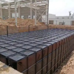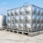
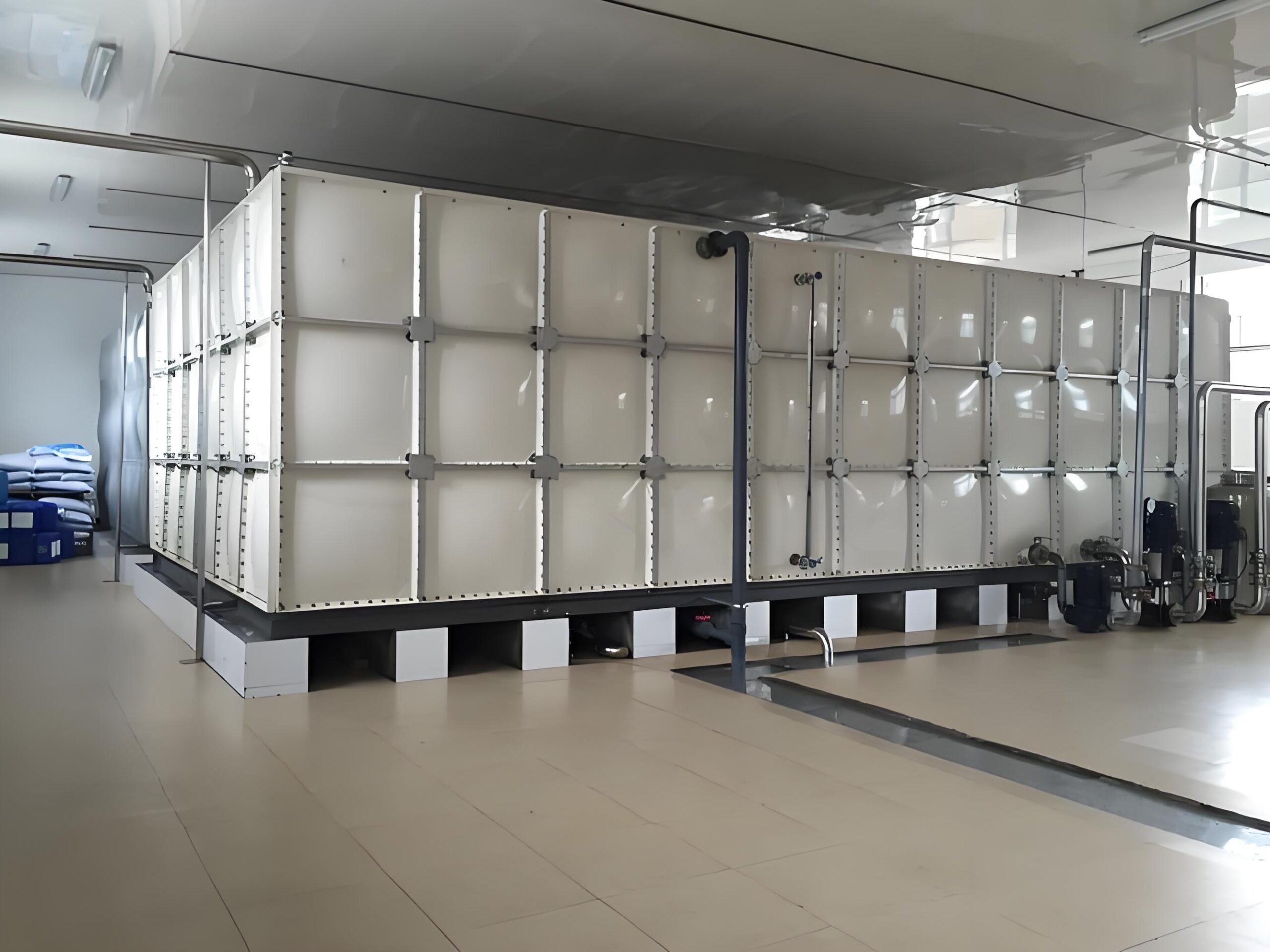
A buried water tank is one of the few structures that is asked to stay put while being pushed upward with enormous force. An empty 100 m³ underground tank displaces 100 tonnes of water — and if the groundwater rises above its base, buoyancy will try to lift it by that amount. Every year, tanks that were installed without proper anti-flotation design crack, tilt, rise out of the ground or float entirely. The good news is that the problem is well understood and entirely preventable with the right design work at the start.
As a water tank manufacturer supplying both above-ground sectional tanks and bespoke buried tanks, we see the same three questions on nearly every underground project: how much uplift force will there be, which anti-flotation method should be used, and who is responsible for checking it. This guide answers all three.
Why Buried Water Tanks Float
Buoyancy is simply Archimedes’ principle applied to a tank: the uplift force equals the weight of the water displaced by the tank’s external volume. A tank is safe when the total downward load — the weight of the tank itself, the water inside it when full, the concrete ballast and any soil sitting on top — exceeds the uplift force with an adequate factor of safety.
The critical condition is not the normal operating state. It is the construction and maintenance condition: the tank is installed, backfilled, but empty, and the water table has risen after heavy rain or a seasonal high. This is the combination that floats tanks.
The Buoyancy Calculation
The uplift force is calculated from the external volume of the tank below the design groundwater level:
- Uplift force (kN) = external tank volume below design water table (m³) × unit weight of water (9.81 kN/m³)
- Resisting force (kN) = tank self-weight + ballast weight + weight of soil above the tank (using the submerged unit weight where the soil is below the water table)
- Factor of safety = resisting force ÷ uplift force
For permanent structures, a factor of safety of 1.5 against flotation with the tank empty is the normal design target; some specifications and local authorities require more. If the factor of safety cannot be reached with self-weight and cover alone, additional restraint is required.
Worked Example
Take a buried tank with external dimensions of 5.0 m × 4.0 m × 3.0 m, installed so that 2.5 m of its height sits below the design groundwater level.
- Volume below water table = 5.0 × 4.0 × 2.5 = 50 m³
- Uplift force = 50 × 9.81 = 490 kN (about 50 tonnes)
- Required resisting force at a factor of safety of 1.5 = 735 kN
- Tank self-weight (say 12 tonnes of structure and fittings) = 118 kN
- Shortfall = 617 kN
That shortfall must be made up by ballast, cover or anchors. This is why anti-flotation design is never an afterthought — on this example the tank’s own weight covers less than a fifth of what is needed.
Method 1: Concrete Ballast Slab
A reinforced concrete base slab cast under or integrated with the tank is the most common solution. Because concrete weighs roughly 24 kN/m³, a slab of the correct plan area and thickness can supply the missing resistance directly. For the example above, about 26 m³ of concrete beneath the tank would close the gap, assuming it stays below the water table where it also displaces water.
Practical points: the slab must be designed to span between the tank supports without cracking, it should be cast as one continuous element where possible, and if the slab extends beyond the tank footprint it can itself attract uplift. When the tank is supplied in panel form, the ballast slab is usually also the tank’s structural base, which is efficient.
Method 2: Soil Cover and Overburden
The weight of soil placed over a buried tank contributes to the resisting force. Two cautions apply. First, soil below the water table must be taken at its submerged unit weight — typically around half its dry weight, which is why saturated backfill provides far less resistance than the same soil above the water table. Second, the cover depth is often dictated by the traffic loading the tank must carry, so it cannot always be increased at will.
Cover is therefore best treated as a contribution rather than a solution, unless the design deliberately uses a deep burial with good, well-compacted granular fill.
Method 3: Tension Anchors and Tie-Downs
Ground anchors or piles connected to the tank base restrain it against uplift. This approach suits sites with high groundwater, restricted plan area or existing structures where a large ballast slab is impractical. Anchors must be designed for the sustained uplift load plus a margin, corrosion-protected for a wet environment, and anchored in a stratum that can actually resist the tension — an anchor into soft clay proves nothing.
Anchors also create local stress concentrations at the connection points, so the tank base and its connections must be designed for them.
Drainage and Groundwater Control
Restraint is only half the design. Controlling water around the tank lowers the load the restraint has to carry. Where site conditions allow, a perimeter drainage system, a granular envelope and a pumped sump can keep the local water table below the tank base for most of the year. This also protects the tank from hydrostatic pressure on the walls during operation, and it makes maintenance access far safer.
Drainage must be designed for the design storm and for a failure case: if the sump pump stops for a week during the wet season, the tank still has to stay down.
Anti-Flotation Design Checklist
- Establish the design groundwater level from borehole data, not from a single site visit.
- Calculate uplift using the external volume below that level, with the tank empty.
- Sum self-weight, ballast, cover and — if used — anchors, applying the submerged unit weight below the water table.
- Target a factor of safety of at least 1.5 against flotation in the empty condition.
- Check the same condition during construction, before the tank is filled.
- Confirm the ballast slab or anchors are designed for the concentrated loads they receive.
- Provide drainage and a controlled dewatering plan for both construction and operation.
- Record the design groundwater level and assumptions for future maintenance work.
For projects where the tank must be installed below ground, our underground water storage tanks are supplied with the base detailing and panel configuration needed to suit the ballast and anchorage design, and we can work directly with the project engineer on the uplift calculation.
Frequently Asked Questions
Does an empty tank float more easily than a full one?
Yes, and this is the case that governs the design. A full tank has the weight of its contents helping to hold it down. An empty tank retains the same external volume and therefore the same uplift force with far less resisting weight, so the empty condition during construction or maintenance is always the critical one.
Can a buried tank be installed above the water table instead?
Where the site allows it, keeping the tank base above the design groundwater level removes the flotation problem almost entirely and is usually the cheapest solution. It is not always possible in coastal areas, flood plains or sites with a high seasonal water table, in which case ballast or anchors are required.
Who is responsible for the anti-flotation design?
Responsibility normally sits with the project’s civil or structural engineer, because the calculation depends on the local ground conditions and the design groundwater level. A good tank supplier will provide accurate weights, external dimensions and base fixing details, and will flag where the supplied information must be checked by the engineer.
Can flotation problems be fixed after installation?
Only at significant cost. Once a tank has lifted, the pipework, joints and base connections are usually damaged and the tank must be dewatered, excavated and re-seated. Retrofitting ballast under an installed tank is rarely practical, which is why the calculation belongs in the design stage — a point every experienced GRP water tank supplier will raise before the order is placed.
Summary
Flotation is a load case, not an accident. Establish the design groundwater level, calculate the uplift with the tank empty, and make sure the combined weight of structure, ballast, cover and anchors exceeds it with a factor of safety of at least 1.5. Get that right and a buried tank will stay where it was put for its entire service life.
Specifying water storage for a project? Contact our team with your capacity, installation depth and ground conditions, and we will advise on the tank configuration and the uplift data your engineer needs.